The 2017 Chevy Volt is a 2nd generation Volt with a bigger battery, and a slightly bigger 3.6kw charger on board. Since we drive the car back home more often than most commuters, we can often charge it in the middle of the day, before we go out again in the afternoon or evening. So, it’s well worth having the faster Level 2 charger. In the first month that we've had the car, we've only used 1 gallon of gas (mostly from a trip going to the airport before the car was fully charged by the little level 1 charger).
The easiest way to choose a charger is to get the one from Costco! They only had one available, so that made the choice obvious. It has no interesting bells and whistles, and I’m not sure I needed any of the other model chargers' bells and whistles, especially since PSE doesn’t vary electric rates by the time of day; and since the 2nd gen Volt has plenty of IOT type controls, and delay charging options built into its Onstar and web based software.
We got the Sieman’s Versacharger with a 240v plug + 20’ charging cord http://www.costco.com/VersiCharge-LVL-2-Universal-Electric-Vehicle-Charger.product.100295506.html
Which is just about $500 after tax, and is covered by the EV Charger rebate program from PSE (which has been extended to April 2017 -- At least according to the advisor that answered the PSE phone line). http://pse.com/savingsandenergycenter/AlternativeFuelVehicles/Pages/Rebate-Qualifications.aspx
There is also a tax deduction for the cost of the EV charger and its installation from the IRS. Gotta keep those receipts.
 |
| Finished Install - outlet recessed in drywall behind the charger (surrounded by the existing wall storage items) |
Since I live in unincorporated King County, WA, there are no city specific electrical codes. King County has no additional electrical codes over NEC 2014; at least as far as adding a new 240v branch circuit into a primary residence.
This is a 30amp unit. And requires a dedicated 40A circuit from your breaker box. As I wanted to locate the charger on the wall right next to the Volt’s charging port, I needed to get a 40A circuit from one corner of the garage to the opposite corner. This is complicated by the full sheetrock covering the garage walls, and the ceiling joists running the wrong way. I didn’t want to deal with drilling through joists, and wanted to minimize drywall repair. So, conduit was the answer. I could have gone with the usual PVC schedule 40 (or schedule 80 for more protection in a garage), but the odd angle bends would have been tricky, and the result would have looked a bit amateur. On the other hand, steel EMT “conduit” looked like it was easy enough to join and terminate, provided more electrical ground protection and superior damage protection for this interior garage usage (even though most of it would be on the ceiling). I decided it was time to learn how to deal with steel conduit!
The 40amp circuit breaker was dictated by the EV charger to be installed. I’m glad my home builder chose a circuit breaker box with a very common breaker that could be found at Home Depot. Apparently, breakers are “standardized” by brand. For a while I worried that I needed some expensive AFCI breaker for a garage outlet. And that is true for 120v outlets in a garage under NEC 2014, but it is NOT true for 240v outlets in a garage; especially one for a dedicated appliance (like a charger). And that goes for GFCI; unnecessary safety/cost for this purpose. I guess the idea is that Americans might use the 120v outlet for some outdoor weedwhacker or for an electric drill building a treehouse and therefore could use the additional safety, but they do not need it for the 240 volt outlet so protected because they don’t make any pluggin tools that use 240 v. I mean, what would they do? Borrow a friend’s MIG welder to put together a steel garden fence? Who in their right mind would do that? :) [It was summertime in Seattle – no rain!]
The next thing I needed to know was the size of the wire to use from breaker box to outlet. I needed to know that which is dictated by NEC 2014: Table 310.15(B)(16) “Allowable Ampacities of Insulated Conductors (no more than 3 current carrying conductors in raceway, cable, or Earth) based on Ambient Temperature of 30C.” I spent some time chasing down possible adjustments to that table. For instance, in conduit of more than 3 conductors, you reduce these numbers by a factor dictated in another table. Also for different ambient temperatures, you need to adjust. But I finally found out that ambient temperatures are dictated by the ASHRAE design temperatures. I found that for Seattle outdoors it’s right below the average for the NEC tables. My application is inside a garage with eastern exposure after you get over 100+ foot tall evergreens. Yeah, I could probably adjust amperage ratings upward.
I bought a little book “Wiring Simplified” on the recommendation from a Home Depot electrician. But found it was targeted for less complicated issues than I was already handling. And it didn’t include the NEC 2014 tables that I wanted in printed form to show the inspector (who in hindsight of course carries his own copy of NEC). Nonetheless, it helped with some mundane questions I had that I felt unfair (without recompense) to ask over the phone of a professional electrician. Like how do you figure out how much amperage your circuit breaker box can handle? Answer: Look at the gauge of the incoming wire and reverse look up Table 310.15B(16) (I see 4/0 but is it THHN? And how many other conductors are in its conduit?). What the heck is this neutral wire and why is it sometimes connected to ground, and sometimes it isn’t. Oh, and circuit breaker boxes aren’t so unknown and scary so more. Well, actually, they are still scary. Especially when you get a tingly feeling when you’re an inch away from live metal. BTW: did you know you can feel 240 voltage a lot easier than 120? I like to think it was my spidey sense, and not because I actually touched anything… The three wires from the service make much more sense to me and the layout of the breaker box with the breakers makes much more sense now (kinda like the first time I pieced together my own PC). For instance, why do some breakers take up 2 slots? The appliance needs 240 v. and therefore needs to get power from both hot wires from the service. The breaker box has two “busses” that alternate hot service wires (out of phase 240v AC) to each slot. So, if you need both, a 2 pole breaker just straddles two slots.
 |
| See the 2 busses behind the breakers? |
Another step of the installation of a new branch circuit is to make sure you’re not overloading your service. That’s why the electrician wiring your house has to have all the specs for all those appliances and lights in your house. I spent a couple of hours looking for that spreadsheet from the original electrician to no avail (the problem with being a determined packrat). Therefore, I had to do a survey of all the electrical items in the house. Fortunately, there are some industry approved shortcuts for the minor electrical items like lights and common plug-in items based on the square footage of your living space (3 watts/sq.ft.), Small appliance load (#outlets in kitchen * 1500w), but then some credits for items that are not used all the time. But then you do need to look up every major electrical appliance/machine; which are all on individual breakers in your circuit breaker box. It got more complicated for me with the emergency generator panel, but I finally figured out how it actually reduced the items shared in my target breaker box. After some careful survey of labels on the appliances and some spreadsheet magic, I found that box uses 152 amps out of ~200 amps available. Yay, my 30 amp constant load charger should be fine! But two Tesla super chargers -- maybe not in my future. That’s OK, we have a backup plan, we tested the welder’s outlet in the workshop and that NEMA 6-30 worked great with the new charger!
 So, I look up 310.15B(16) and see that I only need an 8 gauge THHN conductor for my 40amp circuit breaker (that the length of the run is not the determining factor for wire gauge is confirmed by the charger’s Installation Inspector’s checklist; which Siemens kindly includes online). The minimum size for the wire is set by the expected maximum load (dictated by the circuit breaker limit). You can use a bigger wire for a smaller breaker (and in the future swap the breaker up to the size limited by the conductors). However, lots of internet sources seem to talk about conductor length; at length, to figure out voltage drop. I used Chapter 9, Table 8. [Note, the difference in the two rows of the same gauge wire, is whether or not the wire was solid or stranded.] I calculated about a 1.21 volt drop over 52’ of 8 gauge wire. [ VoltageDrop = I*R = 30amps * (52ft * 0.78 ohms/1000ft) ] That seemed fine; apparently well within normal design limits. Still the less the resistance, the more power efficient your charge.
  |
| 2016 price for THHN conductors at HomeDepot |
Now in parallel to thinking about conductor size, I was trying to future proof this installation in case we get a second electric car with a higher charge rate. For reference, a friend told me he installed 2 Tesla chargers with two 50amp circuits. So, that was my goal, to have a big conduit to go from my breaker box towards the double car bay, and then when it had to break into a box -- someday I could add another branch. I needed that box anyway, because NEC limits conduit bends to 360 degrees before you have to have some conduit body (= box with a screw-on lid (more trade terminology that took some translating)). It took me a long time to figure out why I couldn’t find a conduit body that had wire going straight in and directly out the other side. It’s just a common steel junction box (like you use for switches or outlets).
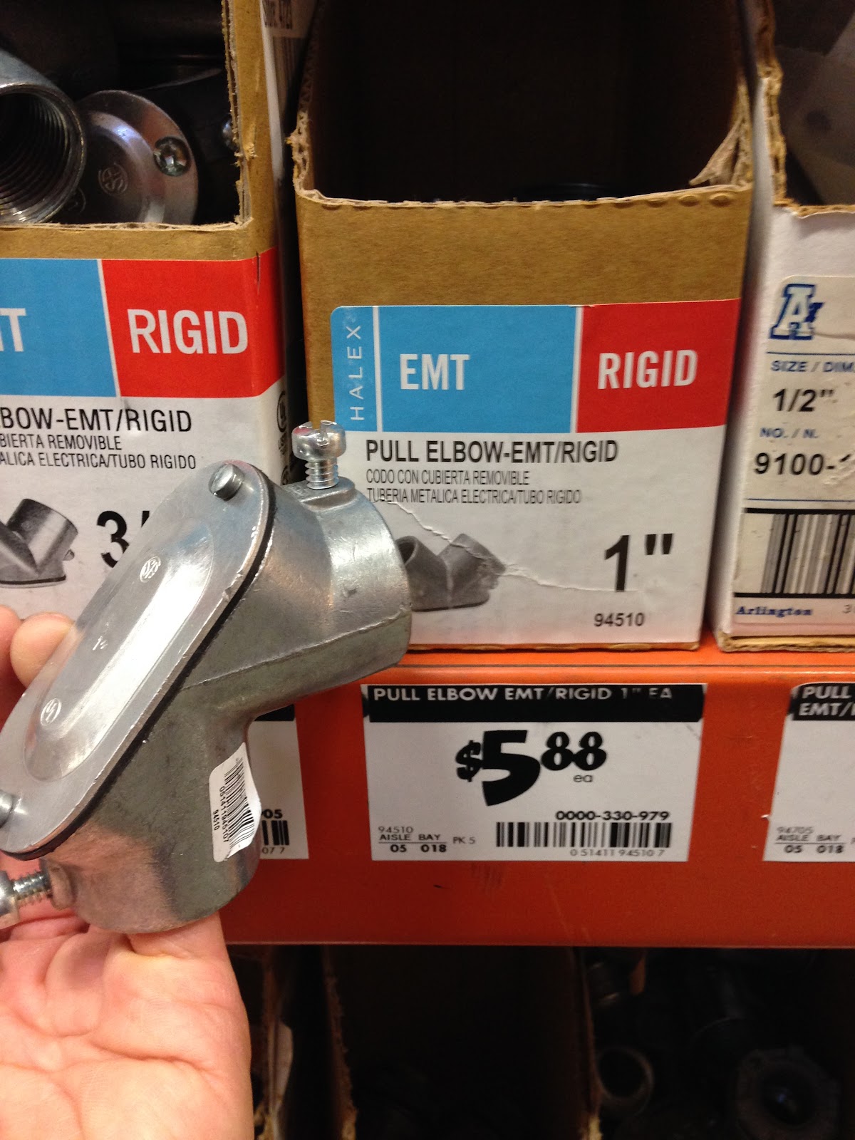 |
| Example of a 90° conduit body |
Now with this dream in mind, I’d need a nice big 1 ¼” EMT conduit. I went to Home Depot and physically saw the size of that pipe… Pipe dream dashed – too damn big and ugly for my garage ceiling (I had to snake through some narrow spaces with the garage door track). So, back to the NEC tables. The NEC limits the conductors you can put into conduit with the ratio of cross sectional area occupied by the wire and air. The idea is that you need some air for cooling, and also some free space in order to pull these wires around the bends of your conduit. I went around several designs where I would have future proofed this conduit for two Teslas, but the answer was to go pretty big. And since I’ve never even touched conduit before this, I thought this might be a risky plan. In the end, I decided on ¾” EMT to allow me to someday allow me to charge a single Tesla with three 6 gauge two phase 240v plus a 8 gauge insulated ground. These are all THHN conductors (for indoors, not for wet locations like THHW), and the cross-sectional area is found in Chapter 9, Table 5. As I was just wiring a NEMA 6-30 outlet which does not have a neutral wire, I thinking of using two 6 gauge for the hot wires, and one 8 gauge green ground wire. The day I need a Tesla level charger, I could just add another 6 gauge for neutral. Add up the areas and prove to yourself it’s less than 40% of the ¾” EMT conduit (use NEC Chapter 9, Table 4). It has to be less than 40% because I used more than 2 conductors in a conduit (Chapter 9, Table 1). Why did I go for a smaller 8 gauge ground conductor? Because bigger wouldn’t fit in the ¾” EMT, and Table 250.122 told me I could (that took a few hours of research to verify that would pass code). Besides, since I was using EMT, and I was intending to ground that sucker properly, which would be a backup for ground.
If I just wanted to support today’s 30 amp charger (and not future proof the conduit), I could have just used ½” EMT. The cost difference between three 6 gauge versus three 8 gauge was just $30, so I figured, why not pay that now.
It seemed like I had a plan now. I heard electricians were booked almost a month out for EV charger installations. It was time to get the permit. Internet browsing told me that King County uses their Labor & Industries department to manage electrical permits. And their website was relatively clear for online permit application for residents. I did call and talk to one of their electrical inspectors for my area to confirm there wasn’t anything commonly missed by homeowners installing an EV charger, and she was mildly encouraging without being helpful on facts about NEC code. The test was: Are you confident you know what you’re doing? The permit was $59; please mention the new branch circuit is for an EV charger.
How did I come up with the 52’ wire estimate? I assumed right angle layout of the conduit, and just used the garage dimension for that swag. However, I really wanted to get fancy with the conduit. There’s a ceiling joist that is 4” proud of the rest of the ceiling. I didn’t want to drill through it; or use 90° bends to go around it (as ¾” conduit takes 6” to bend 90°). At least that’s true using the ¾” conduit bender I had to buy for this project. Please, let me know if you have a project that needs ¾” EMT bent…. This is when I started looking at Youtube videos for bending EMT. They made it look so easy. The math they used was entertaining. It would be so complicated to figure this all out using trigonometry, but the common procedures were all simplified into tables using the assumed common tools of the trade (the conduit bender). It was still complicated, but I learned the main calculations I needed for my project. I attempted the trigonometry for the exact measurements to cut through drywall. That was a long exercise for this student. Which made it all funnier when it came actually using the conduit bender for the first time. Watch this video of my first attempts to bend 3/4" conduit:
I did go back to Youtube to see how this could be so hard. The answer is: use ½” EMT, do this in the summer, it’s much softer; and Asians use a mechanical bender machine.
 |
| Big box offset to get through drywall, and a turn at the ceiling. |
 |
| Small box offset to get to breaker box, and then a rotated turn at the ceiling |
I also learned most all of the calculations I did were nearly useless. I suspect I couldn’t keep the conduit tight to the bender, so the curves were not precise. The measured bend angles were far from precise. In the end, it was a lot of eyeballing curves and test fitting them into the intended spaces.
There was some handwringing for securing the conduit within 3’ of breaker and junction boxes. Fortunately, the 90° curve to the ceiling was smaller when rotated than I eyeballed. Otherwise I was going to have to find the exact requirements on securing conduit (I still wonder how solid that has to be). Also, when I totally missed on the 4 point saddle bend and found I had cleared 5” instead of the targeted 4”, I found I could cut my “beautifully formed” 3 dimensional bend (saddle bend plus another non-planar bend) at a point where I turned them into two 2-d bend sequences. Then I had freedom to rotate the 4 point saddle in its major axis to allow it to hug the ceiling joist (and be secured to it!).
 |
| box offset to box, then 4 point saddle bend, and then an angled turn |
I was happy to find all the EMT connection pieces were on Homedepot.com, and they were standardized enough to fit the breaker box and the junction boxes well. I had to drill a few new holes in a steel junction box to allow for a bigger pair of screws into the wall stud. I don’t know why they didn’t have the equivalent of the PVC renovation junction boxes. And the junction box to NEMA 6-30 outlet was more complicated than I anticipated, due to the fact all the junction boxes just have 2 diagonally opposed screws for their covers, and they use these “mud rings” to bring the box face flush to the drywall. But then the outlet covers don’t match up well to those mud rings. I ended up using my steel saw (nice to have that laying around to cut the EMT too) to chop off corners of the cover to allow access to screws into the junction box. Ugly! I still don’t know how pros would do that (my built-in appliances all use PVC junction boxes in the walls, not steel junction boxes).
After that drywall exercise at the junction box, I decided to cut out a larger section of drywall over the breaker box (including some part over the wall stud). I then cut out the necessary slot for the exiting conduit, and replace the sheetrock with screws back into wall stud.
 |
| Actually, I used a vibrating electric saw to smoothly cut the drywall and not the romex behind it. I only used the razor to finish the cuts. |
Other EMT tips:
- use the “insulated” EMT to box adapter to have a protected edge for pulling wire out of the box – “insulated” just means some plastic around the otherwise sharp-ish edge that wire would be dragged over.] You do not need to buy another plastic nut to protect that edge (as is commonly used to secure PVC conduit to a box.
- To round the edges of the cut EMT, use a 1” diameter grindstone cone shaped drill bit. Wiggle it around for the interior edges. I should have just used a flat file for the outside edges: it was a pain to keep the drill bit steady over them.
- To ground the junction box with the green insulated ground conductor, I started a strip of the cable a few inches from where the cable entered the box, pulled the insulation off only 1 centimeter, but then left the insulation on until it was fed into the NEMA 6-30 screw port. I then bought a nice bracket that pinches the exposed 1cm of wire while screwed into the steel junction box.
When the inspector looked inside that box, he was surprised.
Inspector: Huh! You bonded it!
Me: What’s a “bond”?
Inspector: Did you hire a pro to do this? Did you do this?
Me: yes……
I had to google “bond conduit” to see that it just means you ground the conduit and boxes. I believe that’s the proper practice, even if it’s not required by code. BTW: I did some research on whether or not you can use bare copper for the ground conductor in the conduit. I believe it is not spec’d in code, but again in practice using an insulated ground allows you to test the conduit as a ground conductor; and might be useful to find other shorts in the system should there be a problem in the future.

I only turned off the master switch of the breaker box just before I ran the fishing tape and pulled the 3 wires all at once.
 |
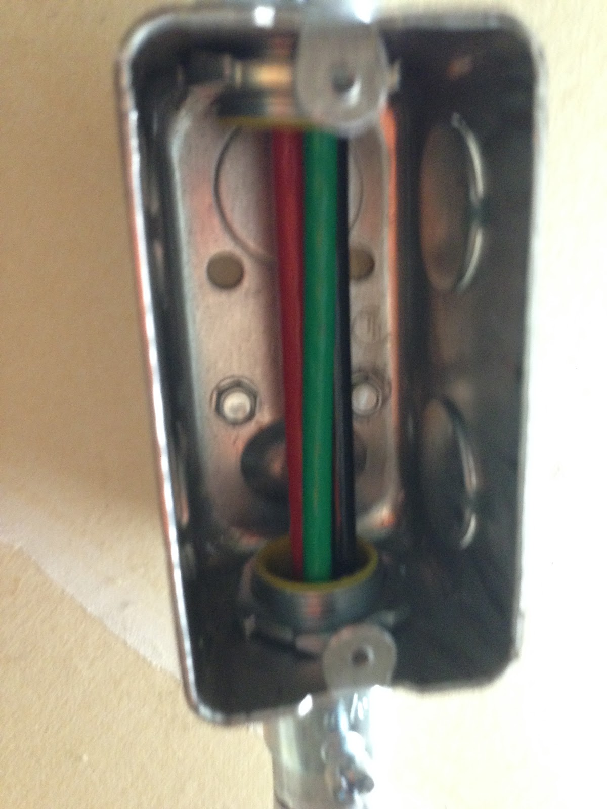
| Just after pulling these wires through with the fish tape head shown |
 |
| I had run the fish tape straight through the middle junction box, since I knew the total bends weren’t too bad, and pulling wire in an out of that little junction box would be harder than just letting it pull straight through. After the wire was pulled through, I went back to add a loop in this middle junction box, just in case... |
 I read and followed advice to run the fishtape from the destination junction box, minimizing the time/exposure of the metal tape in the region of the live service feed at the breaker box. I used a bit of thin cardboard to help make the fish tape head more visible, and protect it from the live service wires also at the top of the breaker box. Since, I did not have nice rolls of wire that could feed into the conduit without twists, I laid out the wires indoors in a clear untwisted line, and walked that back to the garage (with an assistant) to minimize any twists in the wires as they entered the conduit.
 |
| Attach the insulated ground into the neutral/grounding bar to which all the other white and solid bare wires are attached. |

The rest was like wiring any household outlet. Oh yeah, the Red and Black wires are just out of phase hot wires, so it doesn’t matter which goes into the wide plug of the NEMA 6-30. Most Internet sources just say “it doesn’t matter” -- implying: trust us. If I had read the two wires are just the 2 phases of the 240v AC service, it would have made full sense, and not had to rely on trust. [For 120v outlet, the wide plug is the “polarized” hot side, and the narrower plug is neutral.]
It was kinda anti-climatic when I plugged in the EV charger, and it started charging the Volt. It just lights up and works. I guess the glow bar around the charger helps justify the $500 (before rebate) price tag. For materials, tools, and book, I spent $159.64. If I had to guess, I’d say a pro could have done the work (with less care about future proofing, actual amperage limits on the breaker box, drywall and appearance) in 3-4 hours.
